Ladder Logic
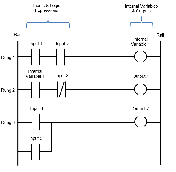
- Meant to diagram relay logic
- or PLC logic
- (which is the same thing, in effect)
Each rung contains the inputs/variables needed to flow current from input (left) to output (right). Pages should have blank rungs to allow for stuff to be added later.
- [?] If this is meant to be digital, why do we make so many pages?
Symbols
As per IEC 61131-3
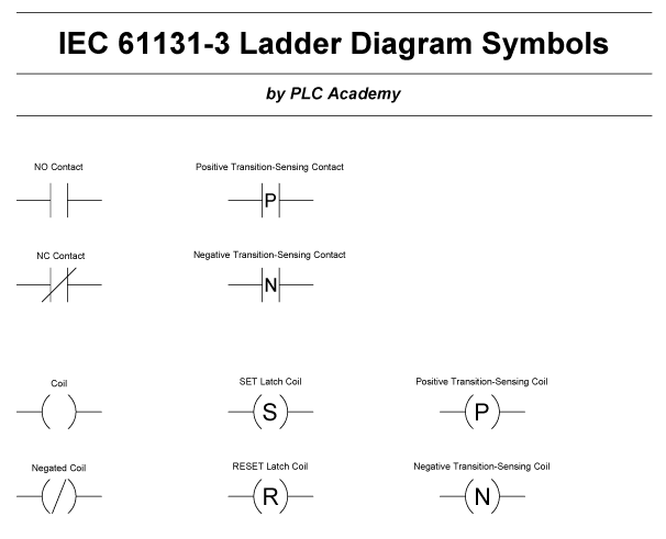
Contact Symbols
| Symbol | Meaning | Symbol | Meaning | |
|---|---|---|---|---|
 |
Normally Open Contact |  |
Positive-transition sensing contact | |
 |
Normally Closed Contact |  |
Negative-transition sensing contact |
Coil Symbols
N.B. Siemens PLCs use Latch/Unlatch in place of Set/Reset
| Symbol | Meaning | Symbol | Meaning | |
|---|---|---|---|---|
 |
Coil |  |
Negated Coil | |
 |
Set latch coil |  |
Reset latch coil | |
 |
Positive Transition Sensing Coil |  |
Negative Transtion Sensing Coil |