electrical drawings
drawings are created in AutoCAD Electrical and are numbered by pages and by lines:
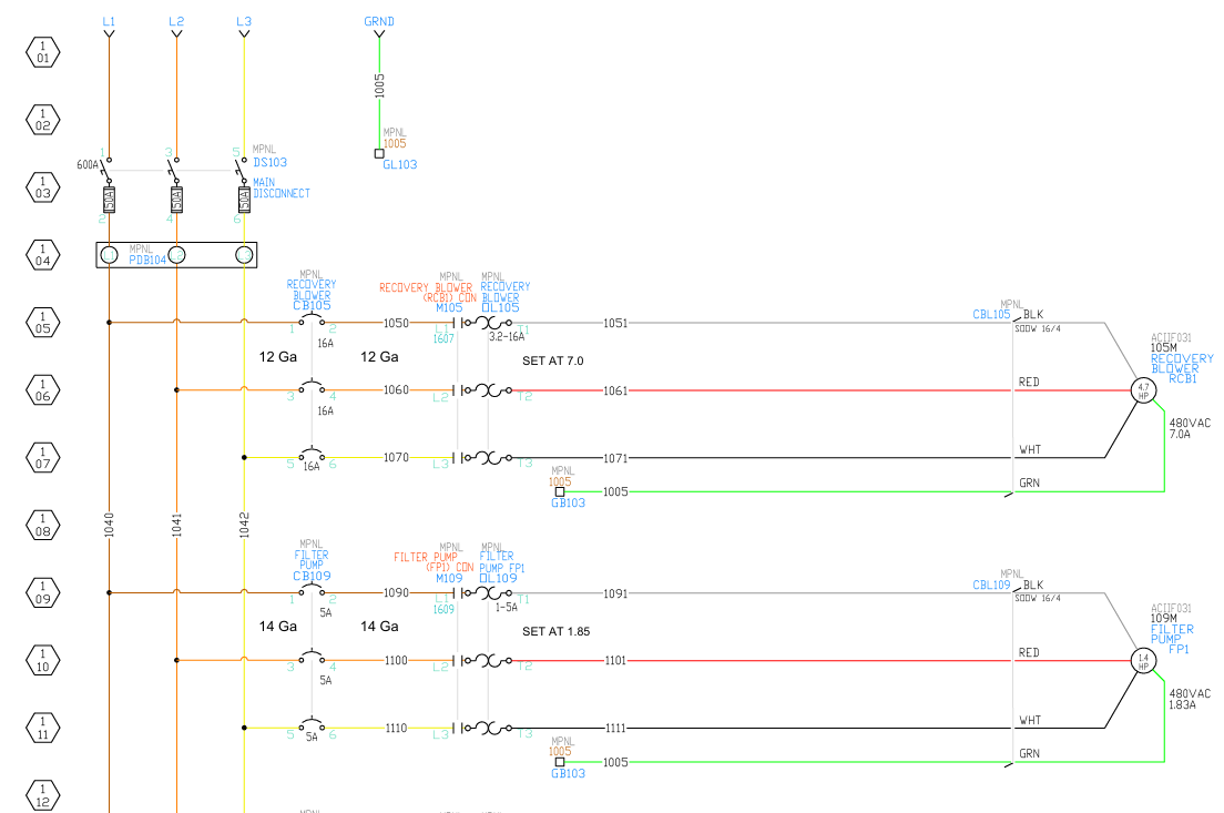
wire numbering conventions
- The hexagons on each side of the page are drawn with a page number over a line number.
- Wire numbers are derived from the line number and page number on which they originate.
- e.g. on page 1, line 09, wire 1040 connects to a circuit breaker and then wire 1090 connects the circuit breaker to the motor's control relay and overload heater. From there, wire 1091 connects the heater to one of 3 inputs to the three-phase motor
- wire 1040 is L1 of the 3-phase 480VAC input, which originates from the terminal block on page 1, line 04.
- wire 1090 is the first unique node on page 1, line 09.
- wire 1091 is the second unique node on page 1, line 09
- e.g. on page 1, line 09, wire 1040 connects to a circuit breaker and then wire 1090 connects the circuit breaker to the motor's control relay and overload heater. From there, wire 1091 connects the heater to one of 3 inputs to the three-phase motor
sheet numbering conventions
drawing sheets are non-consecutively numbered. There is no single standard, two examples are Brian's convention and Steve's conventions, as shown below:
Characteristics applicable to both Systems:
- Page groups which do not apply are omitted.
E.g. a 208 VAC system would start with 208 VAC input lines (L1, L2, and L3) on pg. 1 and all other page number groups would decrement by 10. - If only 2 pages of 24 VDC distribution are required, the pages would number:
and skip the unused page numbers.
Brian's convention
From the mind of Brian Matheny:
| Page numbers | contents |
|---|---|
| 1-9 | 480 VAC distribution |
| 10-19 | 240/120 VAC distribution |
| 20-29 | 24 VDC |
| 30-39 | PLC 1 |
| 40-49 | PLC 2 |
| et cetera |
Steve's conventions
Chart below as created by Steve Kalmar
| Sheet # | Denote | Appendant Name | Description 1 | Description 2 | Comments |
|---|---|---|---|---|---|
| 00 | TOC | Drawing Report | Table of Contents | Lists the Job Name and Work Order as well as any Revision notes | |
| 01 - 09 | ED01 - ED09 | 480_DIST (or 208/240) | Electrical Drawings | 480VAC Distribution | Three Phase power distribution |
| 10 - 19 | ED10 - ED19 | 240_120_DIST (or 208) | Electrical Drawings | 240/120VAC Distribution | Single Phase power distribution |
| 20 - 29 | ED20 - ED29 | 24_DIST | Electrical Drawings | 24VDC Distribution | 24 Volt Control distribution |
| 30 - 39 | ED30 | OPER | Electrical Drawings | MCR Circuit | E-Stop and MCR circuit, CCR circuit if there's conveyor(s) |
| 31 - 39 | ED31 - ED39 | RPNL | Electrical Drawings | Remote Panels | Remote Operator panels |
| 40 - 49 | ED40 - ED49 | PLC_INS | Electrical Drawings | PLC Digital Inputs | Embedded Inputs of Micro800 PLC's, or Input Modules for CompactLogix PLC's |
| 50 - 59 | ED50 - ED59 | PLC_OUTS | Electrical Drawings | PLC Digital Outputs | Embedded Outputs of Micro800 PLC's, or Output Modules for CompactLogix PLC's |
| 60 - 69 | ED60 - ED69 | PLC_EX_INS | Electrical Drawings | PLC Expansion Inputs | Expansion Inputs for Micro800 PLC's, or IO Link Hubs |
| 70 - 79 | ED70 - ED79 | PLC_EX_OUTS | Electrical Drawings | PLC Expansion Outputs | Expansion Outputs for Micro800 PLC's, or IO Link Hubs |
| 80 | ED80 | ENET | Electrical Drawings | Ethernet Layout | Ethernet connections between devices |
| 81 | PL01 | MPNL | Panel Layout | Main Panel | Panel Layout of the Main Control Panel (MPNL) |
| 82 - 89 | PL02 - PL09 | RPNL (or SPNL, or BPNL) | Panel Layout | Remote Panel | Panel layouts of Remote Panels (RPNL), Stage Panels (SPNL), or Booth Panels (BPNL) |
| 90 | BOM | Drawing Report | Bill of Materials | ||
| 91 - 99 | CL01 - CL09 | Conduit Layout | Drawings to assist in laying out conduit or cable trays on site. |